
Questions
- If I have a camera pointing straight down from a UAV what area on the ground will be captured in the image?
- How does this change if the UAV experiences roll/pitch/yaw?
- What happens if this camera is on a gimbal?
Do you have these questions? Well, let’s see the answers.
Preliminary Information
Before we get started it is important to cover a few basics. This tutorial will use the angle units of degrees, distance units of meters, and GPS coordinates in UTM. Basic trigonometry and knowledge of rotations will be an asset.
It is important that when converting from UTM->WGS84 or WGS84->UTM that all of your units start in the same coordinate system. This tutorial will not cover how to convert between units, but it is important that all conversions follow the same math and are reversible. (Don’t obtain coordinates from different sources or formats because they may have used a slightly different conversion method than what you will.)
In this tutorial, we will be using Tait-Bryan angles. This is an angle naming convention so you can personally use whatever you like. The only changes in the math will be a negative sign here and there. Angle Conventions

Basic Ground Footprint
The footprint of a camera pointing straight down is determined by some very basic trigonometry. A camera’s sensor and lens combination will produce a certain angle of view (AOV). You can look this up for your camera. AOV can be broken into a horizontal field of view (HFV), and a vertical field of view (VFV). Check out this Wikipedia page for more info
So from our UAV, we can make a triangle with the ground, using AOV and altitude.

If we cut this triangle, by drawing a straight line from the UAV to the ground, we can get 2 smaller triangles. Each of these smaller triangles is a right triangle so we can use trigonometric identities to solve for distance on the ground.
Now, this is great and all, but it does not take into account the utm location of the UAV nor does it take into account the yaw of the UAV. So let’s do that.
Let’s start by defining two new variables, that represent the distance of the ground from a point directly below the UAV. (in our case this will end up being exactly half of the ground.)
This dx and dy disregard any yaw, so we will need to convert them into x and y in the UTM system by incorporating yaw. (Also called psi in Tait_bryan)
Great now we just need to add that to the current UTM coordinates of the UAV.
So this will provide the first corner of your ground footprint. To get additional corners change the values in equations 4,5. Use the remaining combinations of:
So my UAV is pitching and rolling about, Now what do I do?
Ok, I get you. This is actually really easy since we have no yet included a gimbal. All you need to do is modify equations 4,5 like this:
Let’s include a gimbal
This is where things get complicated. Essentially we have two rotations and there is no simple fix like in 10 and 11. When I first attempted this problem, I tried to take the two rotations, combine them together, and then apply them to expanded versions of equations 10, and 11… but that proved to be a headache. I attempted . The problem is that when you combine the two rotations you are throwing away information on which direction of the image is up. What I learned was that I needed to look at each corner independently and then apply the rotations.
Ok so let’s do it. First, we need to represent each corner as a quaternion. (We will be using quaternions to perform the rotations). Also, I’ll be doing the following section in C#, but it should still be easy to follow along. The source code for the math is linked at the end of this section.
Quaternion TR = new Quaternion(-hfv.Value / 2,  vfv.Value / 2, 0, true);
Quaternion TL = new Quaternion( hfv.Value / 2,  vfv.Value / 2, 0, true);
Quaternion BR = new Quaternion(-hfv.Value / 2, -vfv.Value / 2, 0, true);
Quaternion BL = new Quaternion( hfv.Value / 2, -vfv.Value / 2, 0, true);
Please note that the constructor for the quaternion is converting from euler angles into quaternion representation. There’s an entire wikipedia article on the topic
Next we will create quaternions for the UAV rotation and the gimbal rotation.
Quaternion gimRot = new Quaternion(gimRoll.Value, gimPitch.Value, gimYaw.Value, true);
Quaternion acRot = new Quaternion(acRoll.Value, acPitch.Value, acYaw.Value, true);
Next we will multiply to get new quaternion representations for each corner.
Quaternion TR1 = acRot.Multiply(gimRot.Multiply(TR));
Quaternion TL1 = acRot.Multiply(gimRot.Multiply(TL));
Quaternion BR1 = acRot.Multiply(gimRot.Multiply(BR));
Quaternion BL1 = acRot.Multiply(gimRot.Multiply(BL));
And that is pretty much it. We can now convert back into Euler angles (Remember this link) Once we get back Euler angles, we can utilize roll and pitch into modified versions of equations 4 and 5. Modified versions of equations 6 and 7 will then use the yaw angle we got back from the quaternion.
Then follow up with 8 and 9.
C# Quaternion class used to perform multiplications and conversions
C# Cam Footprint Tester
I wrote a small c# application to test this out.
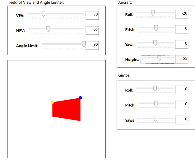
You can find the full code here
The main program file that includes all the steps
Real Life Usage.
I wrote this code for the Paparazzi UAV project. It is written in OCaml. Here is the pull request with all of the relevant files changed.
Thanks for reading. I hope this helps somebody out!!